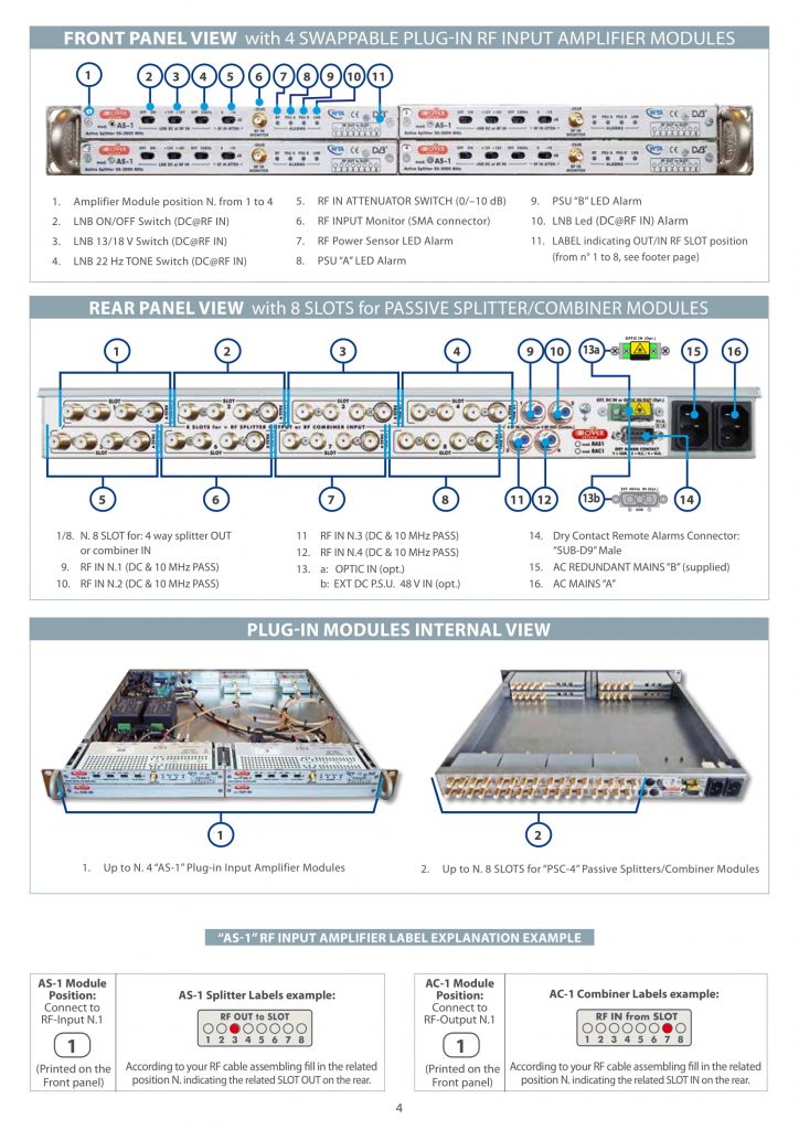
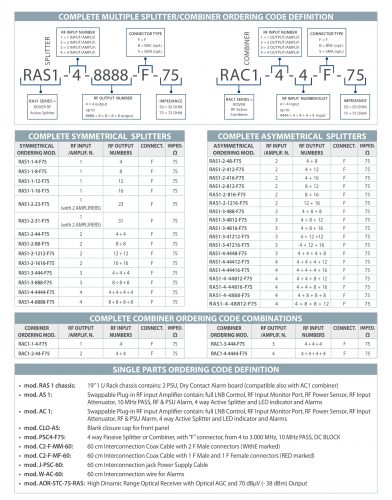
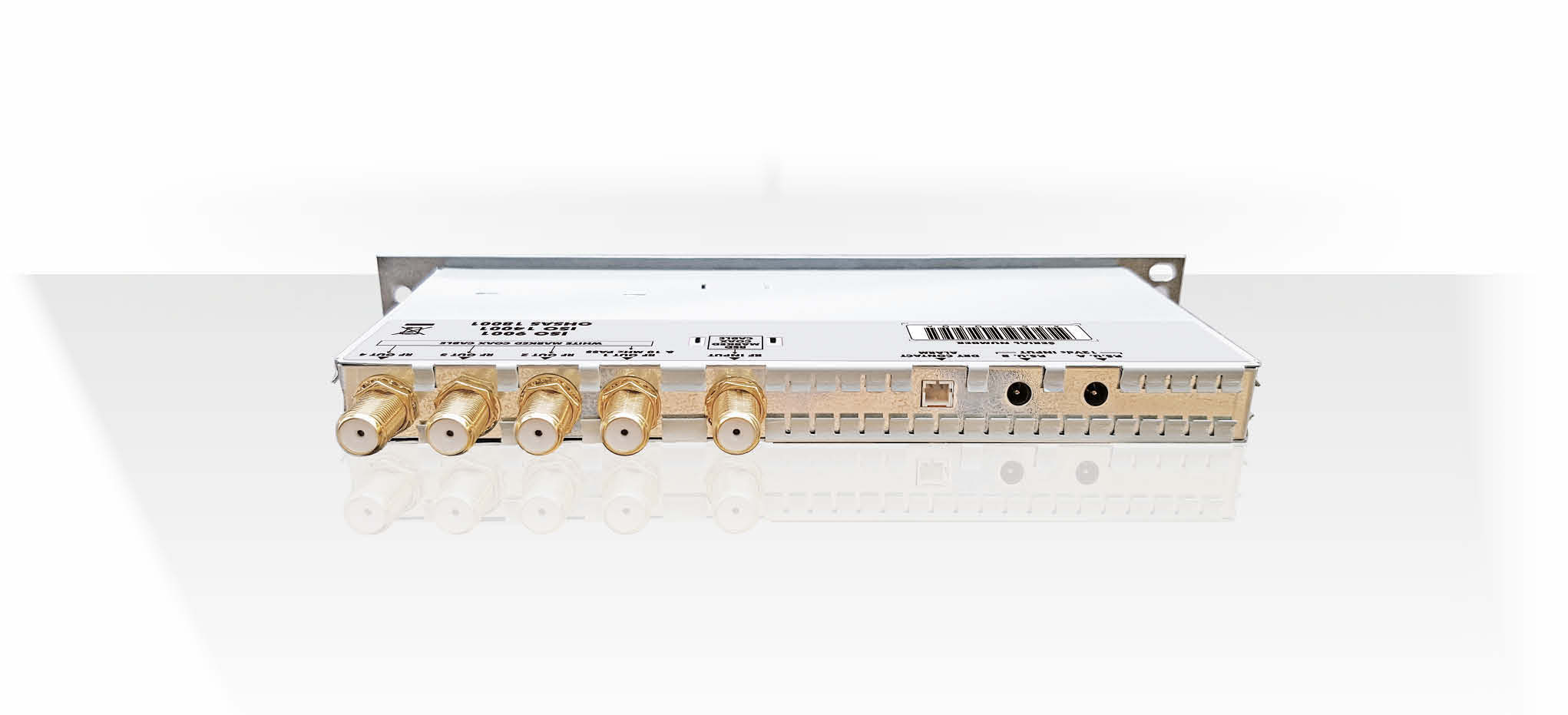
1-4 RF In & 4-32 RF Out, 50-3.000 MHz,
RF Monitor Port & RF Power Sensor,
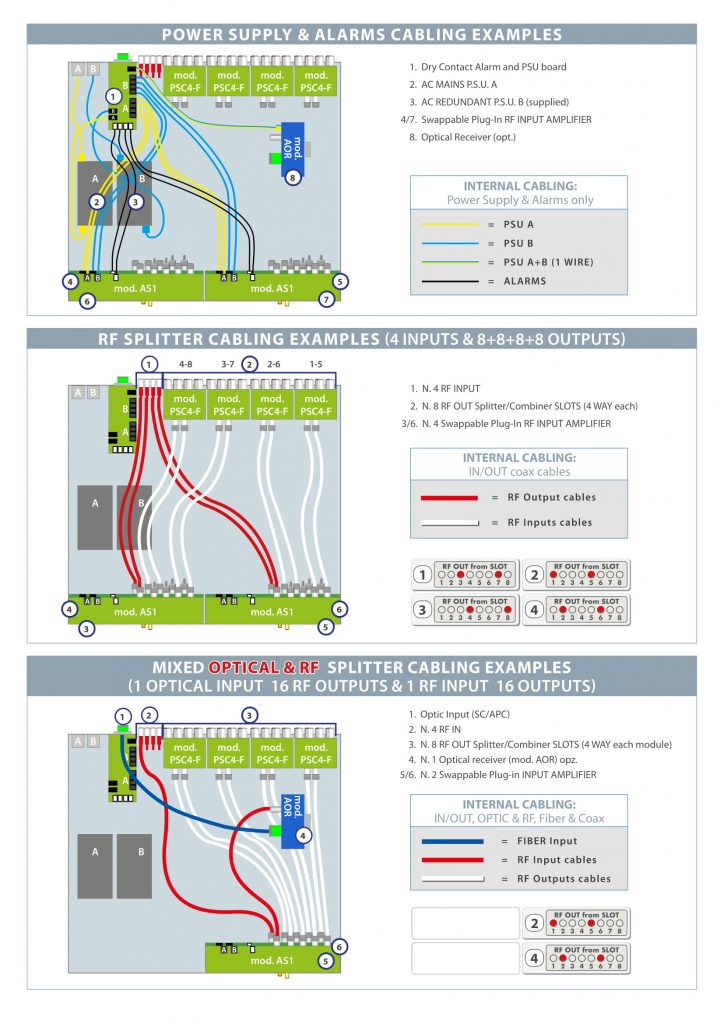
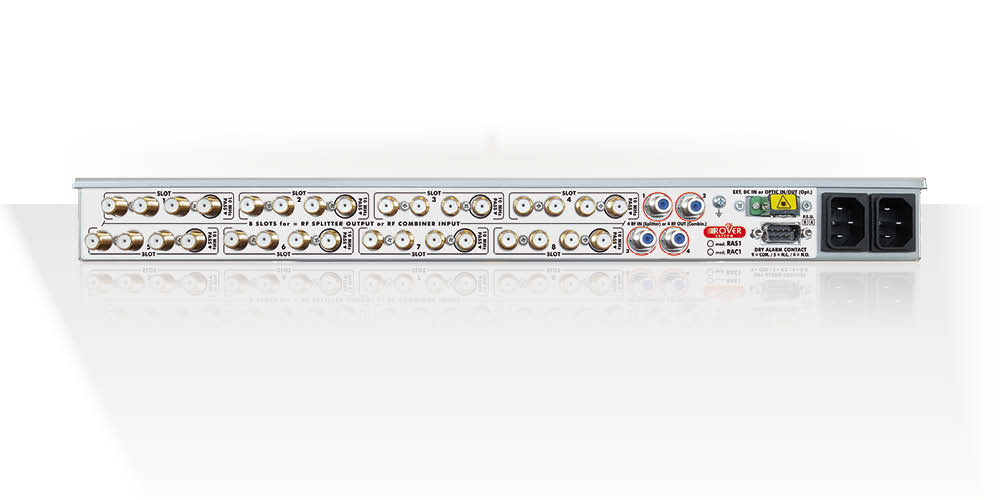
Redundant PSU, Dry Contact Alarms,
opt. Optical In
MAIN FEATURES
MAIN BENEFIT
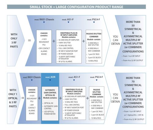
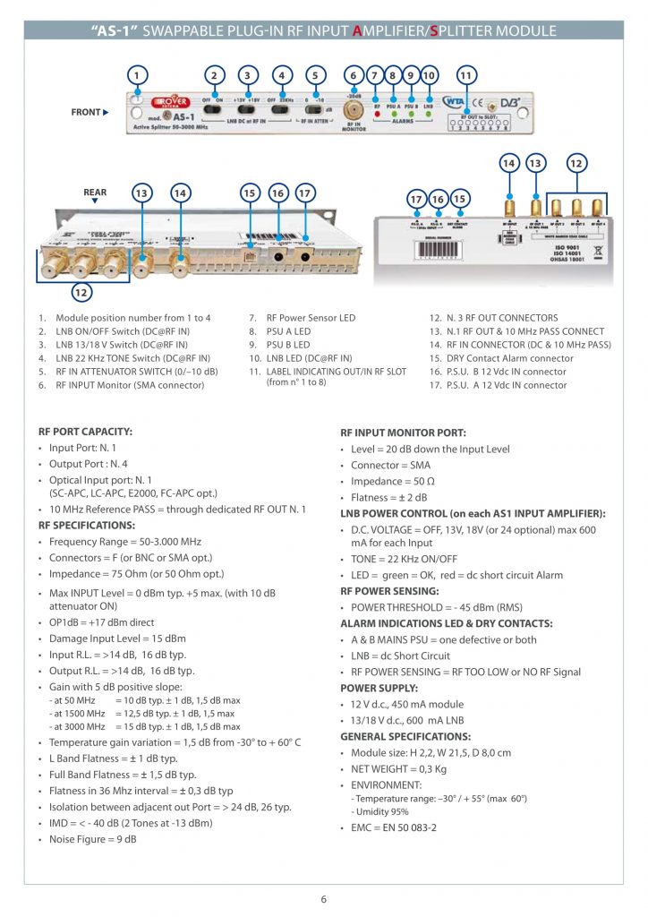
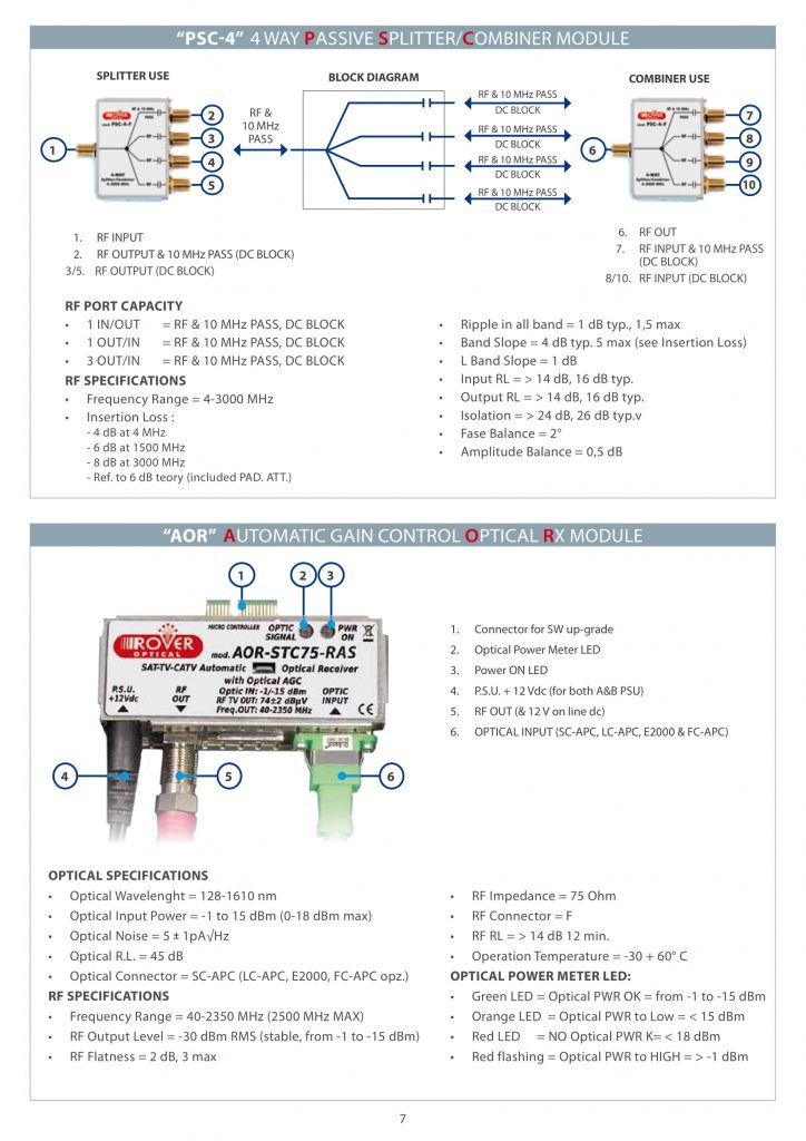
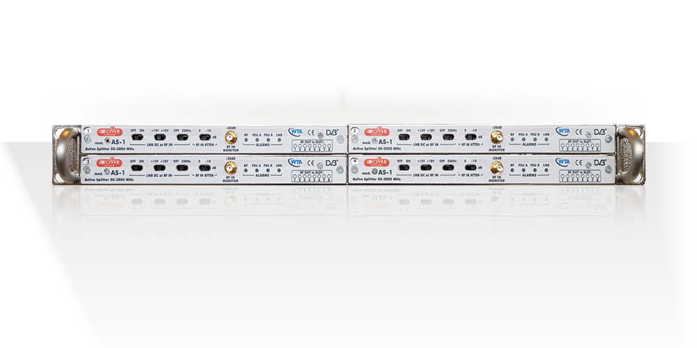
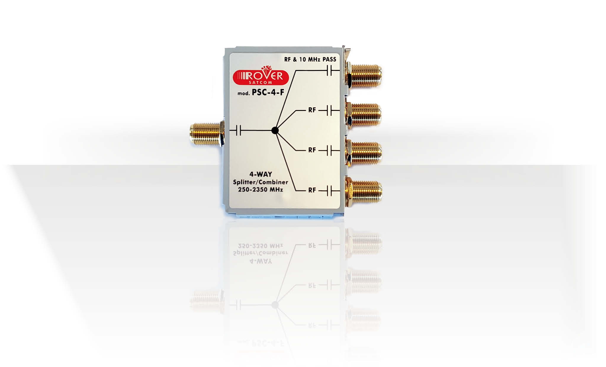
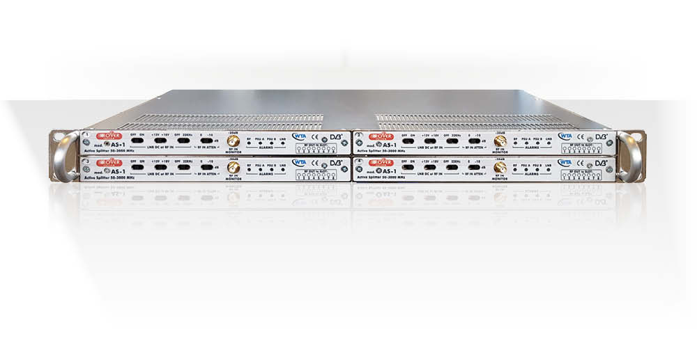
RF PORT CAPACITY:
RF SPECIFICATIONS:
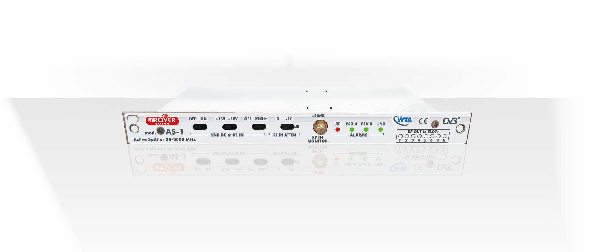
RF INPUT MONITOR PORT:
LNB POWER CONTROL (on each AS1 INPUT AMPLIF.):
RF POWER SENSING:
DRY CONTACT ALARM BOARD:
REDUNDANT POWER SUPPLY:
GENERAL SPECIFICATIONS: