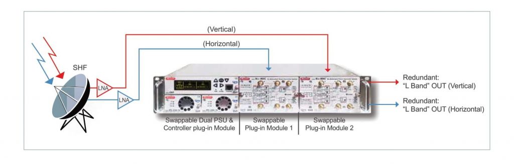
SHF Ku-Band SPECIFICATIONS:
- Dual Band BDC Input =
– L Band 10,7/11,75 GHz
– H Band 11,75/12,50 GHz
- Dual Band BDC Output
– L Band 950/1950 MHz
– H Band 1100/2150 MHz
- Dual Band BDC L.O. Freq. =
– L Band 9,75 GHz
– H Band 10,60 GHz
- Dual Band BDC L.O. = Reference = Built-in
- Dual Band BDC L.O. Leakage = – 60 dBm at SMA INPUT
- Dual Band BDC L.O. accuracy = ± 10 KHz typ. at -30/+70° C
- Dual Band BDC Noise Figure at 12 GHz = 17 dB typ. (20 max)
- Dual Band BDC gain = 10-30 dB internal Adjust, flat ± 3 dB
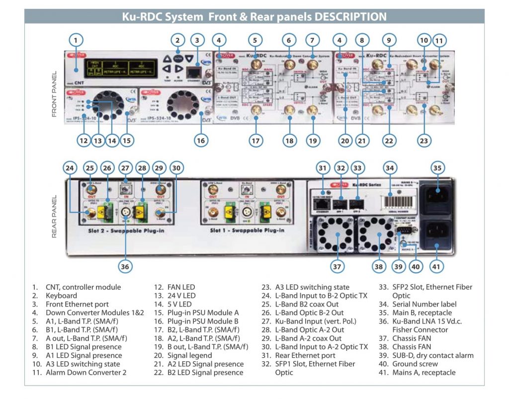
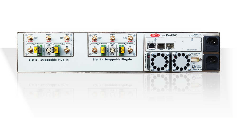
- SHF Ku Input connector = SMA (f) 50 ohm (Rear Panel)
- Dual Band BDC L.O. Phase Noise = 90 dB typ. (80 min) at 10 KHz
RF L-Band SPECIFICATIONS (Plug 1 & 2):
- Output freq. Redundant Low Band = 950/1950 MHz
- Output freq. Redundant High Band = 1100/2150 MHz
- Output R.L. = 18 dB typ. (16 min) SMA connector
- Output RF Connectors = SMA (f )
- Output Optical connector = SC/APC (optional)
- Front panel Test Point = N.3 for Low Band & N.3 for High Band (-20 dB)
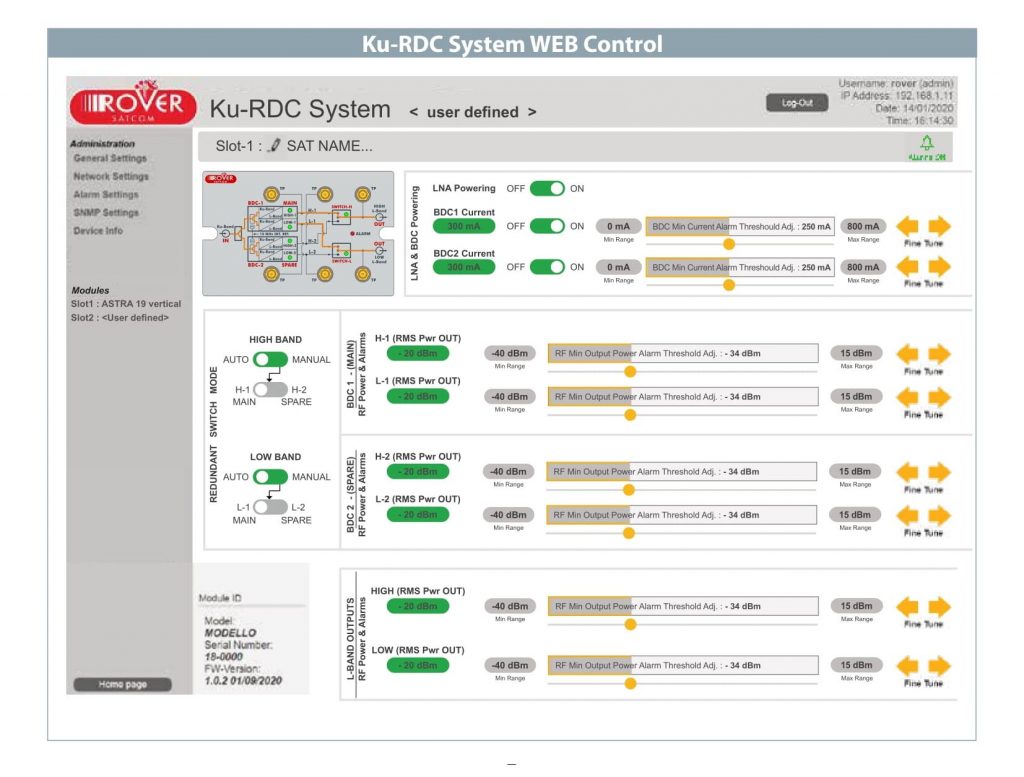
LNA POWER CONTROL:
- LNA Powering ON/OFF Max current 800 mA
- LED = green OK, RED = short circuit allarm
- Alarm indication via LED or dry contact
DRY CONTACT ALARM BOARD:
- CONNECTOR = SUB-D9 Male
- CONTACT LOAD = 65 V 400 mA
- A & B MAINS PSU = One defective
- LNB = DC Short Circuit
- RF POWER SENSING = RF too Low or no RF Signal
REDUNDANT HOT-SWAP POWER SUPPLY:
- N. 2 AC MAINS PSU = 110-240 VAC (with 2 separate receptacle for 2 separate Power LINE)
- AC POWER CONSUMPTION = < 25 VA
- N. 1 EXT DC PSU = 48 V D.C. (optional)
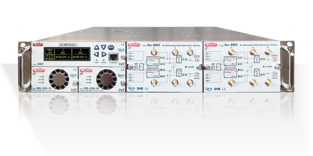
GENERAL SPECIFICATIONS:
- CASE = 19” 2U Rack (43 cm deep)
- NET WEIGHT = from 8 to 12 Kg related to the IN/OUT modules
- SAFETY = EN 50 083-1 and EN 60 950.
- ENVIRONMENT:
– Temperature range: –30° / + 55° (max 60°)
– Umidity 95%
EMC = EN 50 083-2
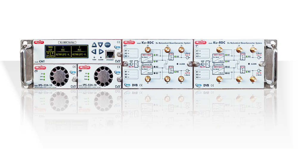
PERIFERALS & CONTROL:
- Local control = with display and front LAN port
- PC control = via front LAN port
- Remote control = via rear LAN port through WEB & SNMP
- Fiber Remote Control via rear SFP Module
- LAN Port = 10-100-1.000 BASE-T