For the HD TAB 4, 7, 700, 900 & 9
For TAB 5 & 7 ULTRA series
For the EASY METER by PRIME DIGITAL series
For the HD LIGHT, COMPACT, FLASH, TOUCH, PRO & PROTAB
The “SAVE DATALOGGER” function allows you to automatically perform all the measurements of the various pre-preset TV and CATV channels within a preset, manual (MANUxx) or automatic (AUTOxx) memory plan.
The measures taken will be saved directly into the internal memory of the instrument and then displayed or printed through the interface program for P.C. “ROVER S.M.A.R.T.” or, only in the models provided, they can be stored in a memory (MEMORY STICK) inserted in the “USB A” port of the instrument.
Please note that the interface S.M.A.R.T. program supports Windows operating systems only and cannot supports MACoperating systems.
Note:
STANDARD PROCEDURE:
1) Turn on the instrument,
2) Make sure you have selected your language,
3) Make sure you have selected the TV or CATV operation mode,
4) Rotate the encoder and select the “MEMORY” icon (see figure 1),
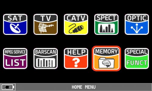 |
| Figure 1: HOME MENU, MEMORY icon selection |
5) Press the encoder to confirm,
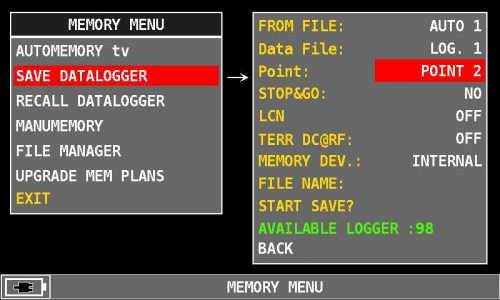
6) Rotate the encoder and select the item “SAVE DATALOGGER” (see Figure 2),
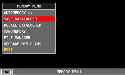 |
| Figure 2: SAVE DATALOGGER selection |
7) Press the encoder to confirm,
8) Press the encoder again and select “FROM FILE:”,
9) Rotate the encoder and select the manual memory plan, eg “MANU 2” (see figure 3) or automatic, eg “AUTO 1” on which to measure (LOGGER) (see figure 4),
 |
| Figure 3: Selecting a manual memory plan, for example “MANU 2” |
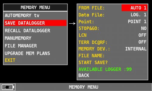 |
| Figure 4: Selecting an Auto Memory Plan, for example “AUTO 1” |
10) Press the encoder to confirm,
11) Rotate the encoder and select the “Data File” entry,
12) Press the encoder to confirm,
13) Rotate the encoder and select “LOGGER” number where saving the measurements, for example “LOG. 1” (see figure 5),
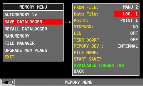 |
| Figure 5: LOG number selection, for example “LOG. 1” |
14) Press the encoder to confirm,
 |
| Figure 6: First free available POINT, eg “POINT 1” |
15) “STOP & GO” function: The “STOP & GO” function is used ONLY if you have stored mixed manual memory plans, ie both TV channels and SAT transponders. If the manual memory plan contains only TV channels, leave the factory default value “NO” if it contains mixed TV CATV and SAT channels select “YES”,
16) “LCN” function: If you want to save the analyzed information on the digital terrestrial channel (MUX), network name, channel name, LCN numbering, etc. Rotate the encoder and select “LCN:”, press the encoder to confirm, rotate the encoder and select “ON” (see figure 7), then press the encoder to confirm,
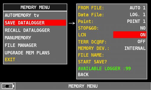 |
| Figure 7: “ON”LCN selection |
17) Power supply “TERR DC@RF”: If required, rotate the encoder and select the power supply voltage to be supplied to the system (preamplifier, line amplifier, etc.): 5V, 12V, 18V or 24VDC And press the encoder to confirm the selected voltage (see figure 8),
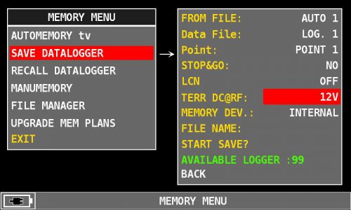 |
| Figure 8: “12V” power supply selection example |
18) MEMORY DEVICE MEMORY DEVICE: If you want to save the measurements directly to an external memory (MEMORY STICK) connected to the “USB A” port of the instrument, press the encoder and select “MEMORY DEV.”: “The “USB” entry (see figure 9, only for the predefined models),
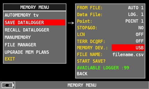 |
| Figure 9: “USB” External MEMORY DEVICE selection |
19) Rotate the encoder and select the “START SAVE” entry (See Figure 10),
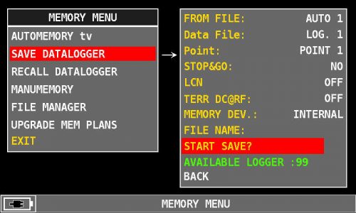 |
| Figure 10: Select “START SAVE?” |
20) Press the encoder to start the measurements,
21) Execution of measures (LOGGER) in progress (see figure 11),
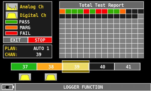 |
| Figure 11: Performing measurements in progress |
22) At the end of the measurements (LOGGER), the word “COMPLETED” will appear, select “RECALL?” and press the encoder if you want to recall and display the measurements (LOGGER) directly on the instrument screen (see figures 12 and 13),
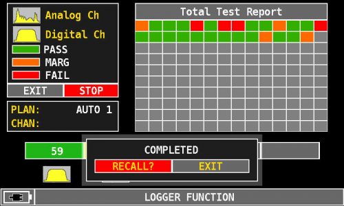 |
| Figure 12: Performing completed measurements, selecting “RECALL?” |
23) Rotate the encoder to navigate between measurements (see figure 13),
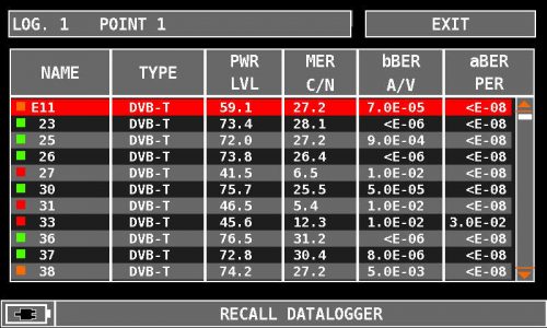 |
| Figure 13: Example of a DATALOGGER recalled directly on the instrument screen |
24) Or select “EXIT” and press the encoder to exit the screen (see Figure 12 and 14),
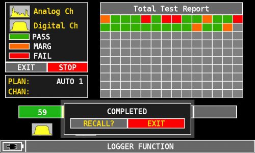 |
| Figure 14: Execution of completed measurements, “EXIT” selection |
 |
| Figure 15: Select “START SAVE?” in the next free “Point”. |
25) If you want to start an additional LOGGER, select “START SAVE” again and press the encoder to confirm.
Note: The MENU (written and graphic) of the figures shown in the following “F.A.Q.” may vary from model to model or depending on SW upgrade.

